
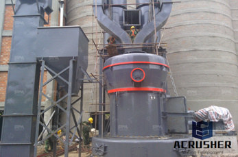
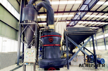
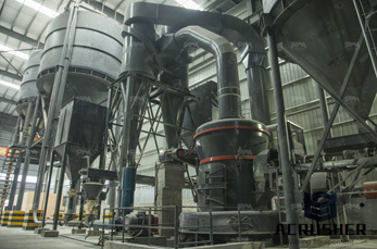
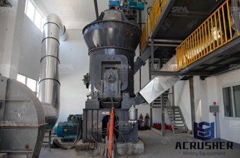
machine grinding symbols values manufacturer Grasping strong production capability, advanced research strength and excellent service, Shanghai machine grinding symbols values supplier create the value and bring values to all of customers.
 WhatsApp)
Introducing the machining surface finish chart, conversion, comparator photos, method, finish degree, Ra, Rz, RMS for iron and steel castings by Dandong Foundry in China.
GDT Symbols Get GDT symbol information at our online machineshop. General CostSaving Machining Tips Download the FREE guide to learn how to:
Surface Roughness symbol in drawing Surface roughness symbol is given to convey manufacturing process related information only. Unless written specifically on the symbol, they do not carry the surface texture type ( plated / milled / cold drawn). These symbols are given irrespective of material and its surface condition.
Jun 21, 2017· Welding Symbols Guide and Chart Fillet Weld and Groove Weld – In order to communicate with others, living being invented a language. A language can help individuals to achieve what they want, and for the larger community to achieve wonder.
grinding energy (u) of 35 Ws/mm3. • The grinding wheel rotates at 3600 rpm, has a diameter (D) of 150 mm, thickness (b) of 25 mm, and (c) 5 grains per mm2. The motor has a power of 2 kW. • The work piece moves (v) at m/min. The chip thickness ratio (r) is 10. • Determine the grinding force and force per grain. • Determine the ...
Dimensions, Tolerance and Related Attributes Dimension – ''a numerical value expressed in appropriate units of measure and indicated on a drawing along with lines, symbols .
Nov 03, 2008· What Do Multiple Triangle Symbols in Surface texture notes mean? Q. Surface texture symbol I notice one to four triangles defining a surface finish. Can you tell me what this means expressed in micro inches, number or microns. Thanks, Sheldon Epstein
Jun 30, 2009· Knowing what manufacturing process can produce surface finishes that desired on a surface can be an added advantage while making the designs. Here is a table showing maximum and minimum Ra values can produced on each production methods.
SURFACE ROUGHNESS TABLES If you want to print this file, then see the PDF format information at the bottom of this page.
Symbol N Finish R a μinch R a μm Super finishing: N1 1 ... 2 N3 4 Grinding N4 8 N5 16 N6 32 Smooth Machining N7
Understanding surface roughness symbols. Symbols that indicate the surface texture of machined and structural parts are used in industrial diagrams. The pictorial representation using these symbols is defined in ISO 1302:2002. This section will explain how to write these symbols to indicate surface textures. Terminology explanation
On the ribbon, click Annotate tab Symbols panel Surface . To place the symbol, do one of the following: To create a symbol without a leader line, doubleclick a location for the symbol. To create a symbol without a leader line associated with geometry, doubleclick a highlighted edge or point. The symbol is attached to the edge or point. To create a symbol with a leader line, click a location ...
If you have not read "9 Basic Steps to Reading Welding Symbols" it may be worth taking a look before continuing with this post. The "9 Basic Steps to Reading Welding Symbols" focuses on fillet welds, but goes thru the basics of the welding symbol (arrow, reference .
Thousands of Used Metalworking and Plastic Machines New Machine Tools Photos, Full Descriptions and Prices Fast Easy : Chip Making Machinery Lathes Mills Drills, Tappers Jig Borers Saws CNC Machining Turning Automatic Screw Machines Boring Mills Broaches Keyseaters EDM''s Grinding Machinery Hones Lapping Machines Finishing Equipment
Optimization of Grinding Parameters for Minimum Surface Roughness by Taguchi Parametric Optimization Technique Deepak Pal, Ajay Bangar, Rajan Sharma, Ashish Yadav Student of (PIS), Mechanical Engineering, Maharana Pratap College of Technology, Gwalior, Madhya Pradesh, India.
are 40 times the values in micrometers The data in the right hand table is furnished only for practical information and to provide an idea of the achievable roughness for different processing methods. This data is primarily for metal surfaces. Other materials may show differences. Basic symbol (without top line) should not be used alone.
Surface roughness is usually specified with a "check mark" symbol on a drawing as shown in the figure below. Surface roughness is typically indicated in RMS or microinches (µin) and is located on the left side of the symbol above the check mark. In the example below the roughness value is 32 RMS maximum and 16 RMS minimum.
Substituting Variable Values in Program Understand how real numbers and integers are treated by the CNC control Real numbers are any number rational or irrational Real numbers include integers, .3765, 5, 10 are all real numbers Integers are whole numbers 2500, 3, 20 Numbers with decimals are not integers Some NC words only allow integers
The principal ISO standard that specifies syrface roughness is ISO 1302 and defines the surface roughness symbology and additional requirements for engineering drawings. The details in ISO surface finish standards relate to surfaces produced by abrading, casting, coating, cutting, etching, plastic deformation, sintering, wear, erosion, and some other methods.
Click the Annotate tab Symbols panel Surface Texture. Select an object to attach the surface texture symbol to. If you attached the symbol to a line, in the drawing area, specify the start point for the leader. If you attached the object to an arc, circle, ellipse or spline, skip to the next step. Specify one or more points to define the vertices of the leader, and then press ENTER.
Surface finish, also known as surface texture or surface topography, is the nature of a surface as defined by the three characteristics of lay, surface roughness, and waviness. It comprises the small, local deviations of a surface from the perfectly flat ideal (a true plane).. Surface texture is one of the important factors that control friction and transfer layer formation during sliding.
Aug 21, 2017· Surface Finish Chart, Symbols Roughness Conversion Tables . Complete Guide to Surface Finish Symbols, Charts, RA, RZ, Measurements, and Callouts ... turning, and grinding, factors such as cutting tool selection, machine tool condition, toolpath parameters, feeds, speeds, tool deflection, cut width (stepover), cut depth, coolant, and vibration ...
Sep 23, 2015· MisUnderstanding Welding Symbols, Part 1. September 23, 2015 Carlos Plaza 4 Comments. Written by: Alicia Garcia. We''ve published several blogs over the years, and while we receive comments on all of them, we''ve noticed a steady stream of feedback on our blogs about welding symbols.
Mar 15, 2018· industrial drawing surface roughness grades symbols tolerance geometry in hindi by gopal sir duration: 12:39. cnc plc training by krishna automation 30,103 views.
WhatsApp)