
gold plant process flow diagram manufacturer Grasping strong production capability, advanced research strength and excellent service, Shanghai gold plant process flow diagram supplier create the value and bring values to all of customers.
 WhatsApp)
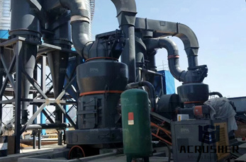
A process flow diagram (PFD) is a diagram commonly used in chemical and process engineering to indicate the general flow of plant processes and equipment. The PFD displays the relationship between major equipment of a plant facility and does not show minor details such as piping details and designations. Another commonly used term for a PFD is a flowsheet
Many modern gold plants incorporate gravity circuits as part of their overall flowsheet, and it is estimated that about 10% of the new gold produced each year is recovered by this technique. The advantages and disadvantages of gravity separation are similar to heap leaching. It is a very simple and low cost process, but gold recovery is usually low
gold mine equipment flow chart – Ore Mining. bentonite wet processing plant pdf · Chromite ore beneficiation plant turkey · XZM Series . You can expect various gold mine equipment flow chart. . Mobile gold mine equipment is made for flexible application in .
The manual is all about VAT Leaching Technology which is a low cost technology for recovery of gold from fresh ore or from tails left from previous CIL process and from Small Scale Miners.
currently operating plant. Process overview and description The CIP process A blockflow diagram of a typical CIP plant for a nonrefractory gold ore is shown in Figure 2. Table I and Table II illustrate the capital and operating cost breakdowns for a typical South African gold plant. These figures are not a standard but reflect the nature of ...
It is a process wherein the casting layer is removed by using different tools like files and burrs. It gives a smooth finish to the piece. Assembly is the process where two or more component of the same design are joint with the help of solder or laser technique . Step # 10 – POLISHING. Polishing offers a neat finish and enhances the value of ...
A flow diagram for fuller''s earth processing is provided in Figure After being mined, fuller''s earth is transported to the processing plant, crushed, ground, and stockpiled. Before drying, fuller''s earth is fed into secondary grinders to reduce further the size of the material. At some plants,
Process flow diagram . A process flow diagram (PFD) is a diagram commonly used in chemical and process engineering to indicate the general flow of plant processes and equipment. The PFD displays the relationship between major equipment of a plant facility and does not show minor details such as piping details and designations.
A process flow diagram pfd is a diagram which shows the relationships between the main components in a flow diagrams are widely used by engineers in chemical and process engineering, they allows to indicate the general flow of plant process streams and equipment, helps to design the petroleum refineries, petrochemical and.
Browse process flow diagram templates and examples you can make with SmartDraw.
Process Flow Diagram For Gold Plant . The process design of gold leaching and carboninpulp . currently operating plant. Process overview and description The CIP process A blockflow diagram of a typical CIP plant for a nonrefractory gold ore is shown in Figure 2.
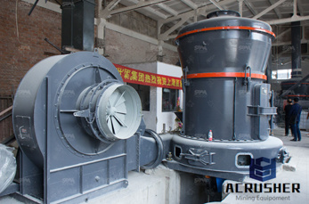
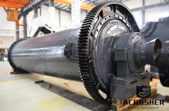
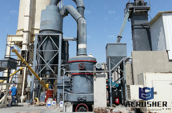
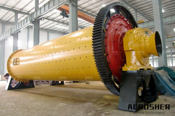
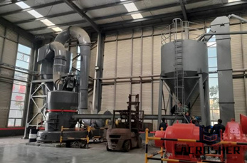
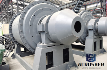
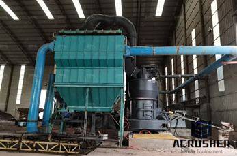
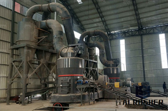
Ore is stockpiled (1) at the processing plant, and the process begins by feeding the ore into a hopper with a loader. The ore is conveyed, and lime is added (2) to raise the pH of the ore. Following crushing through a jaw crusher (3), the ore is fed into the semi autogenous grinding (SAG) mill (4) .
treated in a separate stream at Kopanang Gold Plant. The Kopanang Gold Plant is a modern plant that uses millleachCIP electrowinning processes. The gold from the electrowinning process is smelted centrally in another plant situated 5 km away from Kopanang. The quality of the final bullion is affected by the presence of base metals. This project
Metallurgical ContentLearn CyanidationDevelopments in the CarbonInPulp ProcessDesign Criteria Commercial Operations Cyanide is a lixiviant, or reagent that is used to leach, often in tanks, gold from a solid matrix and form a gold cyanide complex. The gold cyanide complex is then extracted from the pulp or slurry by adsorption onto activated carbon. CIL stands for carboninleach. This is a ...
Gold Mining Plant Process Diagram. The Mining Process. 1. Mining – open pit and underground. This process removes 93% of the gold and 70% of the silver. Water is decanted off and used in the process plant or treated before it is discharged. mining, crushing flow diagram for chromite plant.
CHAPTER 3. ACTIVATED CARBON COLUMNS PLANT DESIGN 119 Linear Velocity = 10 m/h Surface area = cm2 Thus, flow rate is l/h. In the real situation this flow will be 20 l/h, so linear velocity will change, but not too much ( m/h). The other important operating parameter is the empty bed contact time (EBCT), that can be calculated using:
These shapes are known as flowchart symbols. There are dozens of symbols that can be used in a Now; gold mining process flow chartOre plant,Benefication . May 24, 2013· The process flow Technology The process flow diagram.
Oct 12, 2015· Gold Refining process flow explained in details. ... Aqua Regia Gold Refining Plant 6 kg capacity with rotating basket Duration: 2:32. Balestri Technologies 34,476 views.
Aug 05, 2020· The lifecycle of a gold mine. People in hard hats working underground is what often comes to mind when thinking about how gold is mined. Yet mining the ore is just one stage in a long and complex gold mining process. Long before any gold can be extracted, significant exploration and development needs to take place, both to determine, as accurately as possible, the size of the deposit .
A process flow diagram for construction sand and gravel processing is presented in Figure The following paragraphs describe the process in more detail. After being transported to the processing plant, the wet sand and gravel raw feed is stockpiled
Gold ore . Prominer maintains a team of senior gold processing engineers with expertise and global experience. These gold professionals are specifically in gold processing through various beneficiation technologies, for gold ore of different characteristics, such as flotation, cyanide leaching, gravity separation, etc., to achieve the processing plant of optimal and costefficient process designs.
gold and silver flotation processing diagram. this thesis reviews in detail the niche industry of tantalum production .processing the flow and are one of the essential passive components used on circuit .today about of mining and mineral processing
Beneficiation Plants and Pelletizing Plants for Utilizing Low Grade Iron Ore Tsutomu NOMURA *1, Norihito YAMAMOTO *2, Takeshi FUJII, Yuta TAKIGUCHI *3 *1 Technology Process Engineering Dept., Iron Unit Div., Engineering Business *2 Plant Engineering Dept., Iron Unit Div., Engineering Business *3 Ironmaking Dept., Kakogawa Works, Iron Steel Business
Research has shown that it is best to apply agglomeration technology to finely divided metalbearing feed materials. Agglomeration of the fines allows for enhanced, and even percolation of a heap. If left unagglomerated, smaller fines can accumulate in the interstitial areas of larger particles, inhibiting flow of the leaching solution (see figure 2).
WhatsApp)